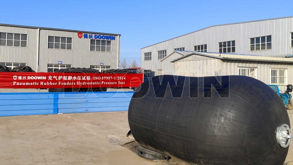
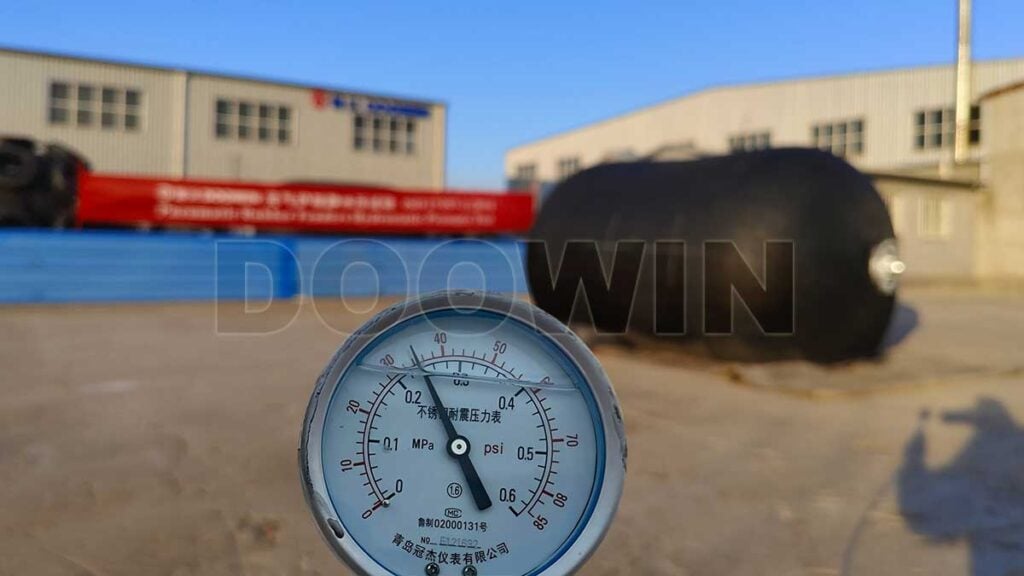
We conducted the hydrostatic pressure test for the commercial floating pneumatic fenders 80kPa Diameter 2.0 x Length 3.5m, based on ISO 17357-1:2014. The entire test was conducted in the presence of the client’s representative and a BV inspector.
1. Test Frequency and Sampling
- General Requirement: 1 test fender shall be selected per every 20 fenders of the same size and pressure rating.
- Small Order Exception: If the order quantity is less than 20 fenders, 1 test fender shall be selected per order.
The customer representative randomly selected a fender for inspection. The fender is evacuated to a vacuum state.
2. Pre-Test Preparation
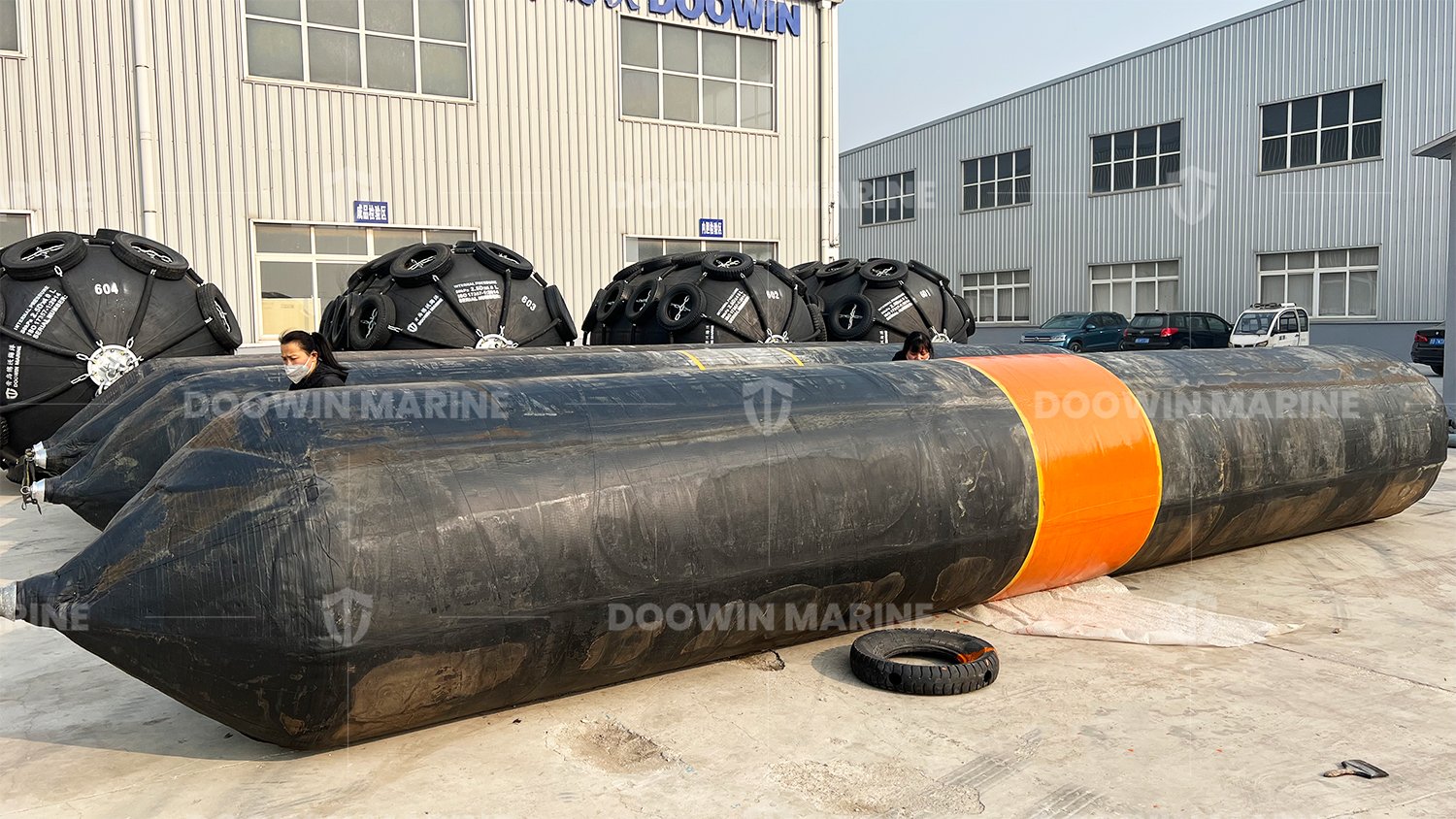
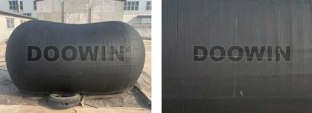
- Measurement Point Marking: Two points shall be marked circumferentially and longitudinally on the middle section of the fender body. The distance between the two points shall exceed one-fifth of the fender’s diameter.
- Initial Measurement: Measure the circumferential length (Lcirc) and longitudinal length (Llong) at 10 kPa pressure, recording these as baseline values.
- Equipment Verification: Ensure the hydraulic pump, pressure gauge (±1 kPa accuracy), and timer are functioning properly.
The fender’s diameter is 2.0m. The distances marked are 502mm.
3. Static Hydrostatic Pressure Test
- Pressurization to Test Pressure: Gradually increase the pressure to the value indicated as “Test pressure at 0% deflection” in Table 4 or Table 5, at a rate not exceeding 0.1 MPa/min.
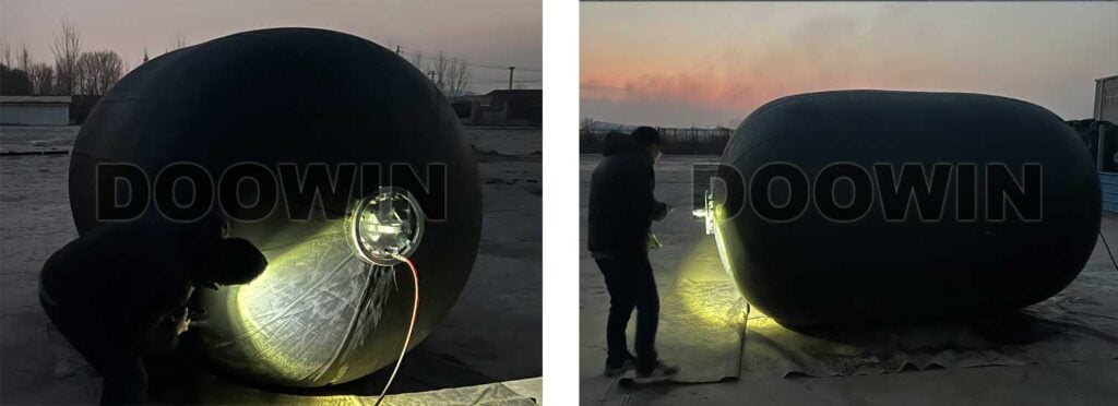
- Pressure Holding Phase: Maintain the test pressure for 10 minutes. During this period:
- Observe the fender surface for water leakage or structural defects (e.g., bulging, cracking).
- Avoid striking or vibrating the fender.
- Leakage Assessment: If no water leakage or visible defects occur during the 10-minute period, the fender passes the airtightness test.
According to Table 5, we fill the fender to the pressure of 250 kPa.
4. Deformation Measurement
- Measurement at Test Pressure: Immediately after the pressure holding phase, measure the circumferential length () and longitudinal length () at the test pressure.
- Temporary Elongation Calculation:
- Circumferential temporary elongation:
- Longitudinal temporary elongation:
- Acceptance Criteria: and .
During the filling water process, we also measured the length under different pressure conditions. Refer to the table below.
| Inner Pressure | ||||
| 10 kPa | 502 | — | 502 | — |
| 105 kPa | 508 | 1.20% | 514 | 2.39% |
| 170 kPa | 514 | 2.39% | 523 | 4.18% |
| 200 kPa | 518 | 3.19% | 526 | 4.78% |
| 250 kPa | 522 | 3.98% | 532 | 5.98% |
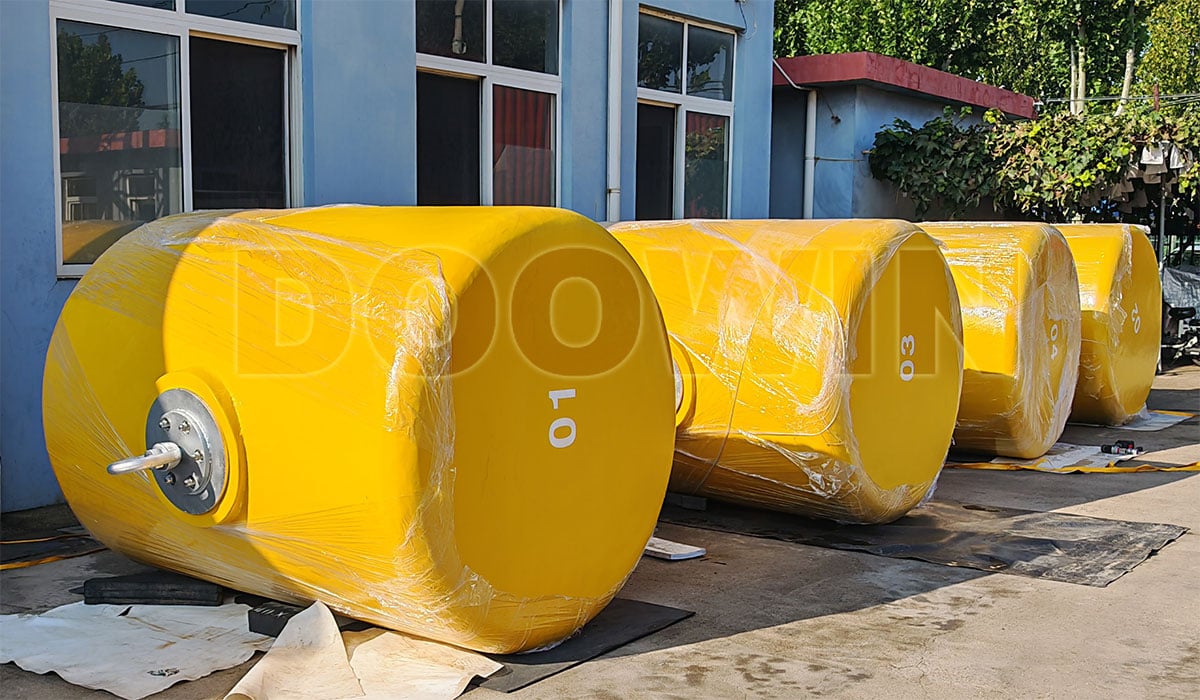
5. Post-Test Procedures
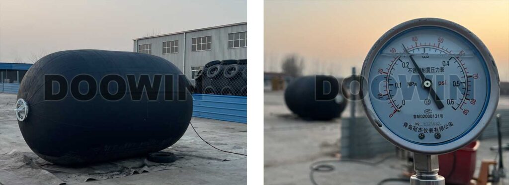
- Depressurization: Slowly release the pressure to 0 kPa to avoid sudden contraction of the fender.
- Data Recording: Document the test pressure, holding time, leakage status, deformation measurements, and elongation rates.-
- When the water pressure was reduced to 10 KPA, we measured the length between the two points again. It had completely returned to the initial 502 mm.
Result determination: all criteria are met, the fenders passed the test.